With the announcement of the Raspberry Pi Zero, I remembered I once wanted to build my own home automation system on top of a IEEE 802.15.4, 6LoWPAN network. I decided to give it another try with the Raspberry Pi zero. By combining the Raspberry Pi zero with 6LoWPAN I hope to create an easy to extend, low power sensor network. With a Pi, it is also possible to utilizing Linux instead of en embedded product and I would be able to leverage my knowledge about Linux and python to easily extend the functionality of my nodes. I've build a first test setup to get 6LoWPAN on linux working with two regular Raspberry Pi B's. This because there is some documentation for getting this setup working and I had two lying around. With this a first proof of concept could be build. It should be easy to migrate this later to a number of Pi zeros because they use the same SoC as the Pi B. Furthermore, in the end, a gateway between my wired network and the 6LoWPAN network is required. A normal Raspberry Pi B or Raspberry Pi 2 would fit this bill since it is low power and has an Ethernet port.
The main reason to use the raspberry pi for this is the small footprint and the lack of unnecessary peripherals. The 40 pin header would also make it easy to attach GPIO driven peripherals such as power meters, relays or temperature sensors. A quick google shows that people connect about anything to the GPIO of the Pi. The other advantage is of course that the Pi zero runs on Linux. It can easily run python applications and other scripting tools. Debugging can be done via a quick ssh session or a serial console if needed and updates should be possible over the air without taking the Pi out of it's tucked away position. For me this is reason enough to go with a board that can run Linux instead of trying something like ContikiOS.
The rest of this blog post will be dedicated to explaining my test setup and how I got there. If something is not clear, do not hesitate to shoot me an email. You can find it in on the about me page. Also mind that this article is written in the beginning of January 2016, things might have changed in the mean time.
Hardware
The hardware I picked for this project is of course two Raspberry Pis as the main board. The IEEE 802.15.4 receivers I picked are two mrf24j40ma. The reason to pick these modules is because they are supported by the Linux-wpan kernel and it looked like it would be easy to solder some headers on them. They were also cheaply available. The mrf24j40 uses the 4 pin SPI bus which can also be found on the headers of the Pi. The integrated PCB antenna will not get you an huge range, but it should be enough for a few meters of unobstructed space. The other hardware needed is the usual to get your Raspberry Pi working, an micro USB power supply, SD-cards, some ethernet cables and some small wiring to attach the modules.
I soldered some pin headers to the mrf24j40ma modules:
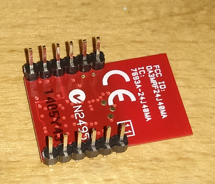
The mrf24j40 module was attached to the Pi with the following wiring scheme. I did not connect the wake pin to anything since it seemed that the kernel driver for the mrf24j40 does not use the functionality. I also connected the reset pin to a 3.3V output of the Pi so It would never get an reset.
| Type | raspberry pi | mrf24j40 |
| Vin | 1 | 10 |
| gnd | 20 | 1 (or 12 or 11) |
| reset | 17 | 2 |
| wake | not connected | not connected |
| int | 16 | 4 |
| sdi | 19 | 5 |
| sdo | 21 | 7 |
| sck | 23 | 6 |
| cs | 26 | 8 |
This table shows the way I connected the mrf24j40 to the Raspberry Pi. Note that the numbers for the Raspberry Pi are pin numbers and not GPIO numbers. Consult a website such as http://pinout.xyz for a layout of the outputs of the Raspberry Pi. The interrupt pin can be connected to any GPIO pin from the Pi as long as that pin is not used for anything else and has a GPIO function. The chip select pin (CS can be attached to either pin 24 or 26 but note whether you used CE0 or CE1, you need it for the device tree file.
Software
My starting point was the minimal Raspbian image. I first got that working to check if the hardware was functional.
Device tree
The problem with the Raspberry Pi, or actually with any embedded board that lacks a BIOS, is that there is no way for the operating system to discover and enumerate the available hardware. The solution for this is device tree. Device tree is a data structure passed to the kernel on boot with a description of the hardware. The data structure itself is passed as an compiled flattened blob to the kernel. With the Pi you can usually find the blob and some overlays on your /boot directory. Overlays are additional device tree files that enhance the passed device tree to the kernel with extra hardware information without having to recompile the kernel or blacklist kernel modules. Mind that the device tree only contains information about the attached hardware. It does not contain drivers or other software. The Raspberry Pi foundation has an excellent article about device tree on their website.
To have our mrf24j40 detected by the kernel, we need to write our own device tree overlay.
1 2 3 4 5 6 7 8 9 10 11 12 13 14 15 16 17 18 19 20 21 22 23 24 25 26 27 28 | /dts-v1/;
/plugin/;
/ {
compatible = "bcrm,bcm2708";
fragment@0 {
target = <&spi0>;
__overlay__ {
#address-cells = <1>;
#size-cells = <0>;
status = "okay";
mrf24j40@0 {
status = "okay";
compatible = "mrf24j40";
spi-max-frequency = <5000000>;
reg = <1>;
interrupts = <23 8>;
interrupt-parent = <&gpio>;
};
spidev@0 {
status = "disabled";
};
};
};
};
|
I'm not going to explain the whole syntax, that can be found elsewhere such as here or here. A few things are noteworthy. First, the spi-max-frequency. This can be at maximum 5Mhz according to the spec of the mrf24j40. The other thing is the "reg" option. This selects the chip select pin that is used for the mrf24j40. I attached it to pin 26 (CE1), but if you want to use pin 24 (CE0), you have to set reg to 0.
The interrupts option specifies the interrupt pin and the interrupt mode. I've used pin 23 for this, but you are free again to pick your own pin. The mode when the interrupt is generated. This should be on a low level for the mrf24j40. The mode is specified by a bit mask, we only want to trigger the interrupt when the mrf24j40 pulls the pin to a low level, so it should be set to 8. A high to low transistion should also works, but the mrf24j40 driver warns against lock ups if you enable that. Documentation for these specification can be found in the Linux kernel documentation.
The above code can be compiled with:
root@rpi:~# dtc -@ -O dtb -o mrf24j40-overlay.dtb mrf24j40-overlay.dts
This should get you an dtb file which is the compiled equivalent of the dts file. Move this file to your /boot/overlays directory. The only thing to be done now is to add the overlay to the dtoverlay config option in /boot/config.txt. My dtb was called mrf24j40-overlay.dtb, so I added the line
dtoverlay=mrf24j40
to config.txt. Note that the file you add to your overlays directory need to end with "-overlay.dtb". Only thing to do now is reboot and your kernel should load the mrf24j40 driver automatically after booting. If this works you should have a line like this in your dmesg:
[ 16.368082] mrf24j40 spi32766.1: probe(). IRQ: 111
If you notice that your Raspberry Pi seems horribly slow (slower than normal), you should check if the linux reports a huge number of interrupts per second. Check vmstat for this. This could mean that your interrupt pin is wrong configured or that there is some problem with it.
After having this working, I found out that newer kernels have better support for 6LoWPAN and that I should use the bluetooth-next branch for this since it contains the development code. So the next thing I did was fix a newer self compiled kernel and get it working on the Raspberry Pi. For that I needed the kernel source and U-boot as an extra boot loader.
Kernel
I checked out the bluetooth-next branch from the kernel. This was version 4.4.0-rc5. I used this config file. If you want to build your own config file, at least make sure that you've enabled the mrf24j40 module and 6LoWPAN support in the kernel. I cross compiled it on my desktop. Cross compiling itself is a bit distribution dependent. In my case there is an excellent article on the Gentoo wiki on how to cross compile for the Raspberry Pi. As far as I could find, U-boot does not support device tree overlays as the Raspberry Pi boot loader does. It thus is also needed to compile a device tree blob with the mrf24j40 module patch in it. The Linux kernel source has the scripts and files necessary for this. The dts files can be found in the arch/arm/boot/dts directory. I patched the arch/arm/boot/dts/bcm2835-rpi-b.dts file to contain:
1 2 3 4 5 6 7 8 9 10 11 12 13 14 15 16 17 18 19 20 21 22 23 24 25 26 27 28 29 30 | /dts-v1/;
#include "bcm2835-rpi.dtsi"
/ {
compatible = "raspberrypi,model-b", "brcm,bcm2835";
model = "Raspberry Pi Model B";
leds {
act {
gpios = <&gpio 16 1>;
};
};
};
&gpio {
pinctrl-0 = <&gpioout &alt0 &alt3>;
};
&spi {
status = "okay";
mrf24j40@0 {
status = "okay";
compatible = "mrf24j40";
spi-max-frequency = <5000000>;
reg = <1>;
interrupts = <23 0x8>;
interrupt-parent = <&gpio>;
};
};
|
This is a bit of an ugly patch, but it works :) The dts files can be compiled to dtb files with:
hydrazine@dystopia ~src/bluetooth-next % make ARCH=arm CROSS_COMPILE=/usr/bin/armv6j-hardfloat-linux-gnueabi- dtbs
Your CROSS_COMPILE variable might be different, depending on your distributions cross compile implementation. The kernel itself can be modified and build with:
hydrazine@dystopia ~src/bluetooth-next % make ARCH=arm CROSS_COMPILE=/usr/bin/armv6j-hardfloat-linux-gnueabi- menuconfig
hydrazine@dystopia ~src/bluetooth-next % make ARCH=arm CROSS_COMPILE=/usr/bin/armv6j-hardfloat-linux-gnueabi- -j$NUMBER_OF_CORES
Note that you MUST also set the CROSS_COMPILE and ARCH variables when using menuconfig or you will get the wrong configuration options. After building, copy the compiled zImage from arch/arm/boot/zImage and the device tree blob from arch/arm/boot/dts/bcm*.dtb to the /boot of your SD-card. Installing modules can be done with the following command if you've mounted the root filesystem of your Raspberry Pi somewhere accessible
root@dystopia ~src/bluetooth-next/ # make ARCH=arm CROSS_COMPILE=/usr/bin/armv6j-hardfloat-linux-gnueabi- INSTALL_MOD_PATH=$PATH_TO_RPI_ROOT modules_install
U-boot
Because the vanilla kernel does not include the patches needed to get a kernel working on the Raspberry Pi without a separate boot loader, U-boot is necessary. U-boot is a boot loader often used on embedded devices. U-boot normally handles the first steps of booting an embedded device, but with the Raspberry Pi there is already a boot loader contained in the start.elf binary. In this case, U-boot is more a secondary boot loader chained from the Pi boot loader.
I built a U-boot image on my desktop. I have not yet verified whether the U-boot from the Raspbian sources works out of the box with the needed features. I took swarren's U-boot branch. According to elinux.org he is working on the Pi support in U-Boot and his branch should contain some Pi specific patches. Building U-Boot took me not much more than:
hydrazine@dystopia /usr/local/src % git clone https://github.com/swarren/u-boot.git
hydrazine@dystopia /usr/local/src % git checkout -b rpi_dev origin/rpi_dev
hydrazine@dystopia /usr/local/src % cd u-boot
# Configure u-boot
hydrazine@dystopia /usr/local/src/u-boot % make ARCH=arm CROSS_COMPILE=/usr/bin/armv6j-hardfloat-linux-gnueabi- rpi_defconfig
# build u-boot
hydrazine@dystopia /usr/local/src/u-boot % make ARCH=arm CROSS_COMPILE=/usr/bin/armv6j-hardfloat-linux-gnueabi- -j$NUMBER_OF_CORES
With this a Raspberry Pi compatible u-boot binary should be build. Copy the u-boot.bin image to the /boot of the Raspberry Pi. To let the Raspberry Pi boot loader start our u-boot binary instead of directly starting the kernel, the kernel parameter in config.txt need to be changed to u-boot.bin:
kernel=u-boot.bin
u-boot needs some instructions about what to boot next. I created an u-boot.scr file. This contains the instructions for u-boot.
setenv fdtfile bcm2708-rpi-b.dtb

mmc dev 0
setenv bootargs earlyprintk console=ttyAMA0,115200 console=tty1 rootwait
setenv bootargs ${bootargs} root=/dev/mmcblk0p2 dwc_otg.lpm_enable=0
load mmc 0:1 ${kernel_addr_r} zImage
load mmc 0:1 ${fdt_addr_r} ${fdtfile}
bootz ${kernel_addr_r} - ${fdt_addr_r}
This file needs to be converted to an u-boot.scr.uimg. mkimage (installed with the u-boot-tools package) is used for this:
hydrazine@dystopia ~ % mkimage -A arm -O linux -T script -C none -n boot.scr -d boot.scr boot.scr.uimg
I had some problems with setenv and long lines, so I split it over two lines to get it working. The first load command loads the kernel (named zImage) from the /boot directory. Change it if you named your self compiled kernel different. The "fdtfile" is the flattened device tree file compiled with your kernel source. The final bootz command boots your kernel with the device tree. If everything is working, you should get a booting Raspberry Pi that first shows some U-boot information, followed by a booting kernel.
If it doesn't work, check the output of u-boot when booting. I've had no problems with it except some minor things like incorrect filenames. It often gives sufficient information about what it is trying to do and what the problem is.
Wpan-tools
With this working, wpan-tools is next. wpan-tools is the user space tooling to control the IEEE 802.15.4 devices. It can be found at the wpan website. Compiling and installing the wpan-tools is not much more than make and make install. You need the libnl-3-dev package on debian to build it.
With wpan-tools build and installed the IEEE 802.15.4 device can be configured. For example check the output of "iwpan phy":
root@rpi:~# iwpan phy
wpan_phy phy0
supported channels:
        page 0: 11,12,13,14,15,16,17,18,19,20,21,22,23,24,25,26
current_page: 0
current_channel: 17,  2435 MHz
cca_mode: (2) Carrier sense only
cca_ed_level: -69
tx_power: 0
capabilities:
        iftypes: node,monitor
        channels:
                page 0:
                        [11]  2405 MHz, [12]  2410 MHz, [13]  2415 MHz,
                        [14]  2420 MHz, [15]  2425 MHz, [16]  2430 MHz,
                        [17]  2435 MHz, [18]  2440 MHz, [19]  2445 MHz,
                        [20]  2450 MHz, [21]  2455 MHz, [22]  2460 MHz,
                        [23]  2465 MHz, [24]  2470 MHz, [25]  2475 MHz,
                        [26]  2480 MHz
        tx_powers: 0,-0.5,-1.2,-1.9,-2.8,-3.7,-4.9,-6.3,-10,-10.5,-11.2,-11.9,-12.8,-13.7,-14.9,-16.3,-20,-20.5,-21.2,-21.9,-22.8,-23.7,-24.9,-26.3,-30,-30.5,-31.2,-31.9,-32.8,-33.7,-34.9,-36.3
        cca_ed_levels: -90,-89,-88,-87,-86,-85,-84,-83,-82,-81,-80,-79,-78,-77,-76,-75,-74,-73,-72,-71,-70,-69,-68,-67,-66,-65,-64,-63,-62,-61,-60,-59,-58,-57,-56,-55,-54,-53,-52,-51,-50,-49,-48,-47,-46,-45,-44,-43,-42,-41,-40,-39,-38,-37,-36,-35
        cca_modes:
                (1) Energy above threshold
                (2) Carrier sense only
                (3, cca_opt: 0) Carrier sense with energy above threshold (logical operator is 'and')
        min_be: 0,1,2,3
        max_be: 5
        csma_backoffs: 0,1,2,3,4,5
        frame_retries: 3
        lbt: false
Supported commands:
        * new_interface
        * del_interface
        * set_channel
        * set_pan_id
        * set_short_addr
        * set_backoff_exponent
        * set_max_csma_backoffs
        * set_max_frame_retries
        * set_lbt_mode
        * set_ackreq_default
        * set_tx_power
        * set_cca_ed_level
        * set_cca_mode

root@rpi:~# iwpan dev
phy#0
      Interface wpan0
              ifindex 3
              wpan_dev 0x1
              extended_addr 0xf2a58a9f6cab2814
              short_addr 0x2244
              pan_id 0x3364
              type node
              max_frame_retries 3
              min_be 3
              max_be 5
              max_csma_backoffs 4
              lbt 0
              ackreq_default 0
iwpan splits the configurable device into phy and a wpan devices. The settings under the phy are the hardware specific settings of the radio. The settings under the dev contain the interface specific setting. Thus the phy controls more or less the radio settings such as the transmit power and channel and the dev the interface specifics such as the mac address and the pan id.
Networking
To configure your interfaces for actual networking, a lowpan type interface is needed. As far as I understood, the lowpan interface behaves as an regular IPv6 compatible network interface where the wpan interface is the IEEE 802.15.4 interface. For example, the lowpan interface reports an MTU op 1280 octets, where the wpan interface reports the 123 octets MTU of IEEE 802.15.4. To start, pick an 16 bit pan id, for example something like this should give you a random pan id.
hydrazine@dystopia ~ % sudo dd if=/dev/random count=1 bs=2|hexdump
Also, pick a channel which you want to contaminate with extra RF. The following list of commands should give you a working lowpan interface:
# set your channel
root@rpi:~# iwpan phy phy0 set channel 0 $CHANNEL
# create the lowpan device
root@rpi:~# ip link add link wpan0 name lowpan0 type lowpan
# Set the pan id of the device
root@rpi:~# iwpan dev wpan0 set pan_id $PAN_ID

# set interfaces up
root@rpi:~# ip link set wpan0 up
root@rpi:~# ip link set lowpan0 up

# Make sure you use your own ULA range (Don't copy this one exactly)
root@rpi:~# ip address add fdcf:1c10:a3d1:432e::/64 dev lowpan0
If you have done this with two Raspberry Pis it should be possible to ping them from each other. If you don't know the exact mac address (or you're lazy like me) pinging the IPv6 multicast all nodes address should also work:
root@rpi:~# ping6 -I lowpan0 ff02::1
PING ff02::1(ff02::1) from fe80::f0a5:8a9f:6cab:2814 lowpan0: 56 data bytes
64 bytes from fe80::f0a5:8a9f:6cab:2814: icmp_seq=1 ttl=64 time=0.317 ms
64 bytes from fe80::2883:cde0:f3cc:fa7f: icmp_seq=1 ttl=64 time=12.2 ms (DUP!)
Two replies are received, one for each node. With this, you should also be able to ssh to the other note, assuming it runs an ssh server. If you want to ssh to the link local address you can do that with:
root@rpi:~# ssh fe80::2883:cde0:f3cc:fa7f%lowpan0
Currently, I run a simple Radvd on one of my border router to enable SLAAC on my 6LoWPAN network. I achieved speeds of around 80-100kbit over the wireless link and around 6 meters of range before I ran out of clear space in my room. At 6 meters I had some packet loss while pinging, but not enough to disrupt a TCP connection.
With this I have a simple 6LoWPAN network up and running. Of course, this is only the beginning. A lot of stuff still needs to be done. If you check "lsmod", you can see that a number of next header compression module are loaded and in use by the 6lowpan module. But a lot of things are not yet supported. For example the neighbor discovery optimizations for 6LoWPAN or a decent routing protocol to have multihop routing. Still, this is a start and most networking is possible.
Remarks and other stuff I encountered
SPI speed
I initially set the SPI max speed of my SPI interface really slow, around 10kHz. The reason for this was because I didn't trust the wiring between the Raspberry Pi and the module. This slow speed gave some problems when sending over large packets. I didn't notice any problems with ping, but when trying iperf the test would not start, or with ssh, the connection would stop after "debug1: SSH2_MSG_KEXINIT sent". Upping the speed to the maximum of 5MHz solved any issues with this.
Interrupt amount
Once I had everything connected in which I thought was the correct way, I noticed that my Pi was really slow, and with that I mean REALLY slow. Like needing to wait for Vim to scroll to the next line of a file. Checking vmstat, I noticed a large number of interrupts per second, around 10000. In Top, the "spi32766" process ate around 25% cpu. This was caused by an incorrectly attached interrupt wire, or incorrect attached SPI interface.
SPI connection
Apparently, If you don't connect the SPI interface correctly, it shows up in the dmesg output with SPI timeout messages. Check dmesg if you suspect your SPI wiring.